|
Roger Garland |
In order to improve the handling and safety of the 26C it is advisable to modify the rudder to make it a more ballanced and larger rudder.
Moving the leading edge forward three inches makes the steering easy. It is like power steering but it still retains the safety of the tiller going to leward if it is released. It does not reduce the weather helm but it reduces the pull on the tiller.
The original rudder is undersize and and in windy conditions it becomes overpowered resulting in the boat rounding uncontrollably into the wind. Adding to the area of the rudder minimizes this tendency. The boat can be sailed at a greater angle of heel. Heeling the boat farther is bad for sailing performance but at least the boat stays under control. The boat also tracks better when reaching with a good breeze and a sea.
Listed below are several ways to modify the rudder.
1. The front edge can be built up with bondo (The stuff that is used for body work on cars) I have modified my original rudder this way and it works better than the original but it was not made longer so it still is on the small side.
2. Lou Daviau added to the front with bondo and also added to the length by making a plaster cast of the bottom and then filling the mold with bondo and setting the rudder into it.
3. Buck Robbins modified his rudder by inserting a piece of wood into the rudder. His description is below.
Simply cut the rudder length wise about 2.5 inches back from the leading edge. Cut from the bottom to about a inch or so below the hole for the hold down cable. Using West Systems epoxy, sandwich a 2X4 in between the two pieces. leave enough sticking out the bottom so that you can restore the bottom edge shape. Use fiberglass cloth and epoxy to fair the whole thing. Fill all voids and sand. I then painted mine with CSC anti-fouling paint since my Mac stays in the water.
Buck
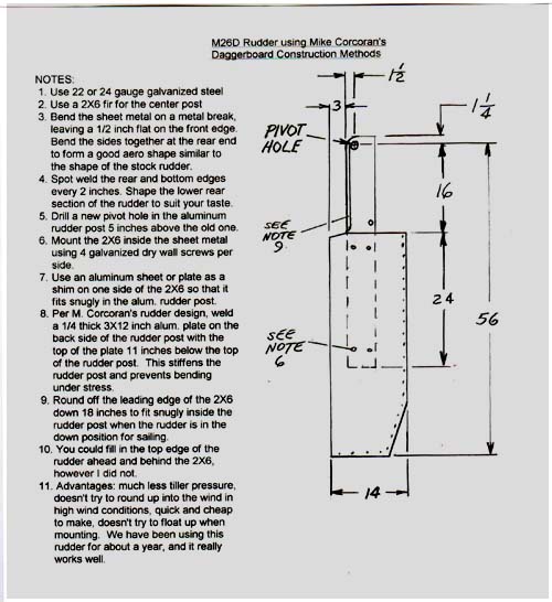
4. Brian Atwood made a rudder out of sheet metal as shown in the drawing below.
5. There has been talk about using the original rudder and bending sheet metal around it. The sheet metal could extend 3" beyond the original and be epoxyied and screwed to the fiberglass. This would allow adding 4 inches to the length for better control. The bottom could have a wood piece shaped to give strength to the bottom or the bottom few inches could be filled with foam. This would brevent the metal from being damaged if it hit bottom.
6.Many people have built a new blade out of wood. A soft wood is not strong enough but almost any hardwood will do. The preferred types are probably woods that have traditionally been used for boat construction such as mahogany or oak.
Mike Corcoran and I have built many rudders and below is our latest thinking. They are similar but have slight differences.
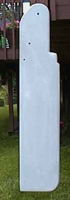
My rudder is shown here.
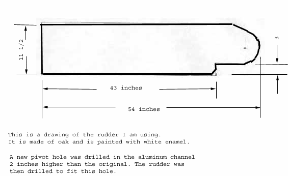
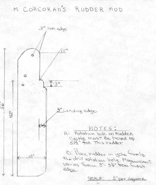
Mikes rudder is shown here. The total length is 56" and the rudder is 14 1/2 into the channel. This leaves 41 1/2 below the channel. The fore to aft dimension is 12"
FOIL SHAPE
Steve Vaczovsky was kind enough to send me the formula for a NACA 0012 foil.I believe this is the best shape for a rudder and tried to make my rudder to this shape.
NACA foil sections can be copied from a table that represents the dimension
measured from a center line (to only one side - you must mirror image the
other side) from specific "station" points. Station points begin at zero
at the nose. They are listed as percentages of the full foil width (called
c) and are more frequent near the nose since that is where the curve
changes more rapidly. The table lists X (distance from the nose listed as
a % of c), and Y (distance from the center line of the foil to the wing
surface, again as a % of c). You can thus use the table to scale for any
width foil.
At the nose, the curve change is so rapid, the leading edge is approximated
by a quarter circle with a radius of 1.6% of c.
I converted all my measurements (c, x and y) into millimeters for ease of
using the % multiplier and used metric rules to lay out my template
(actually a jig which was used to support a router with an 1/8 bit. You
can shape the whole blade in about an hour with a perfect shape. The jig
does take about an hour to make, but once made can be used over and over.
When I build a rudder this winter according to Mike's specs, I will make a
jig that will last and perhaps pass it around to those on the list who are
interested in building his rudder. One drawback is these numbers do not
include the thickness of the fiberglass, but the next one I make I may just
only paint and figure on making a new one every few years.
Steve Vaczovsky
 For a NACA 0012 the table is:

X               Y
2.5             2.6
5               3.6
7.5             4.2
10              4.7
15              5.4
20              5.7
30              6.0
40              5.8
50              5.3
60              4.6
70              3.7
80              2.6
90              1.5
100             .1
These figures are rounded from numbers that are 4 significant figures, but
with a relatively small wing (say 12") you cannot measure, let alone shape,
a form that accurately. Remember these measurements were made to lay out
airplane wings. You can see from the table the max cord depth is at 30%
which from my reading is the preferred location for max lift with the least
drag.
M26C "Dreamtime"
Sacramento, CA BACK